Now, at various points during the strip down, there were moments of WTF.
Particular ones that spring to mind include where someone had rammed a self tapping screw through the radiator supports to stop the radiator being able to rattle around, the number plate light “bracketry” and the electrical tape around the vacuum T-piece.
But all of that was trumped by the rear suspension.
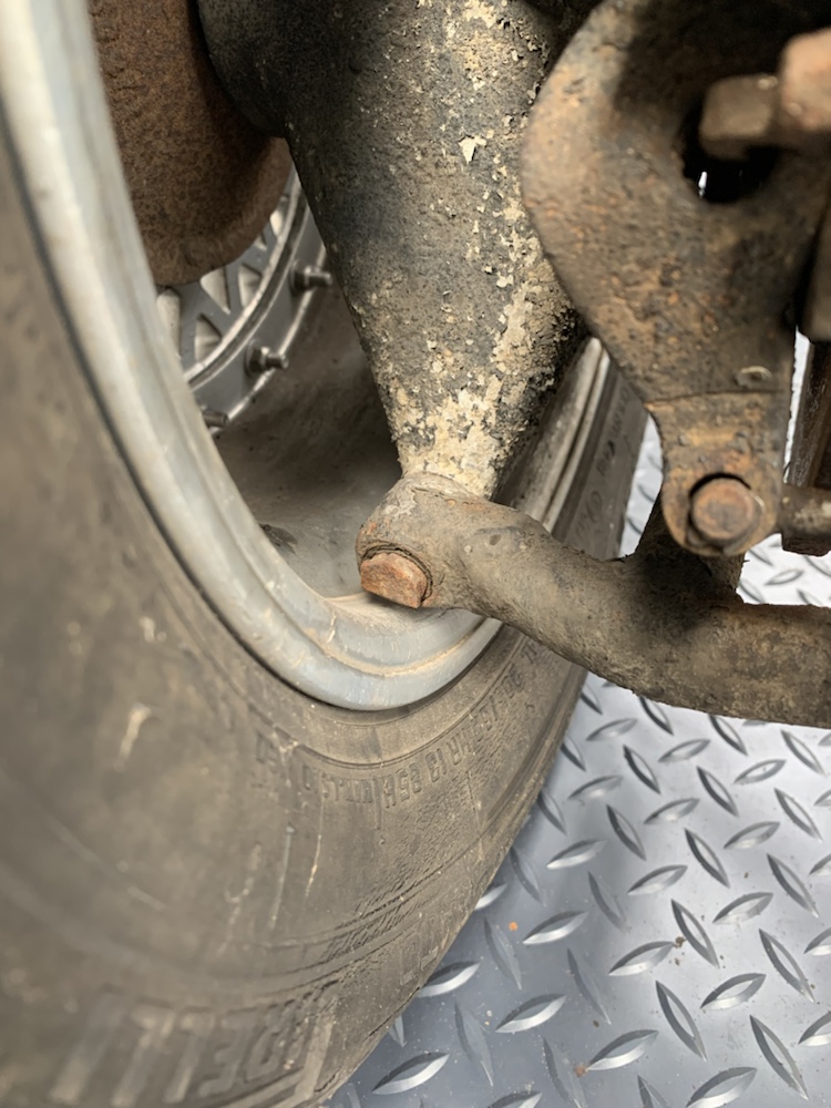
I know the wheels are far wider than stock, but they’re also 3 piece split rims. You can specify and adjust the offset pretty comprehensively. Instead, someone has elected to fit overly wide inner barrels and take a grinder to the bolt heads where the bearing carrier bolts up to the wishbone.
Clearance up top has been achieved with some blacksmith style “heatin’ and beatin'”
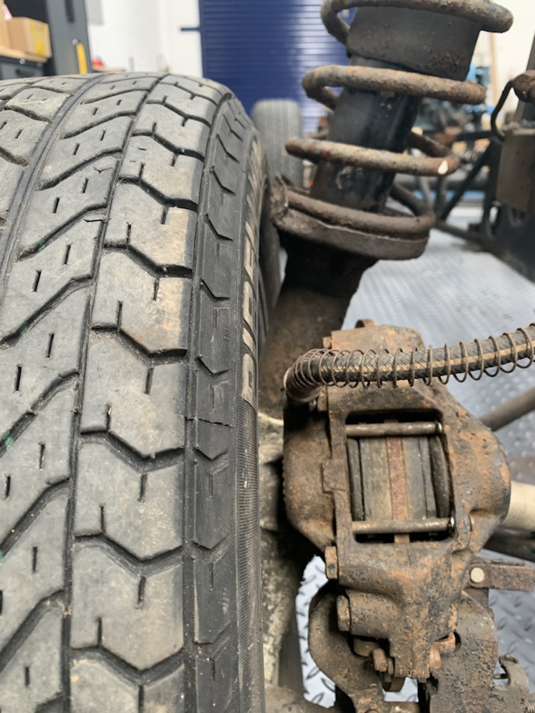
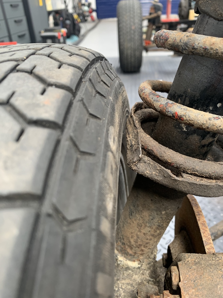
The spring platforms on both sides, comprehensively remodelled, despite doing what they could with some custom “spacers.”
I don’t have many pics of the engine removal process, was a little busy/involved with the process of getting it out to pause for pictures.
Will need to get my act together and pull a video together as I know I have some footage, certainly the bit where I rattled my head off the engine crane was captured!
With the engine and box removed, there’s not a hell of a lot left. Having only really worked on far more modern machinery prior to this, the overwhelming thought when working through the chassis and suspension was just how dainty everything is.
The steering rack on the Elan is mounted forward of the front axle line. The tie rods and rod ends will need replaced, rubbers weren’t perished but felt very old and will be replaced at the same time.
Front double wishbone set up has been modified, the wishbones look to be Spyder manufactured tubular steel items, where original Lotus ones were made from steel plate. The front damper assemblies are height & damping adjustable Avo units from the mid-late nineties.
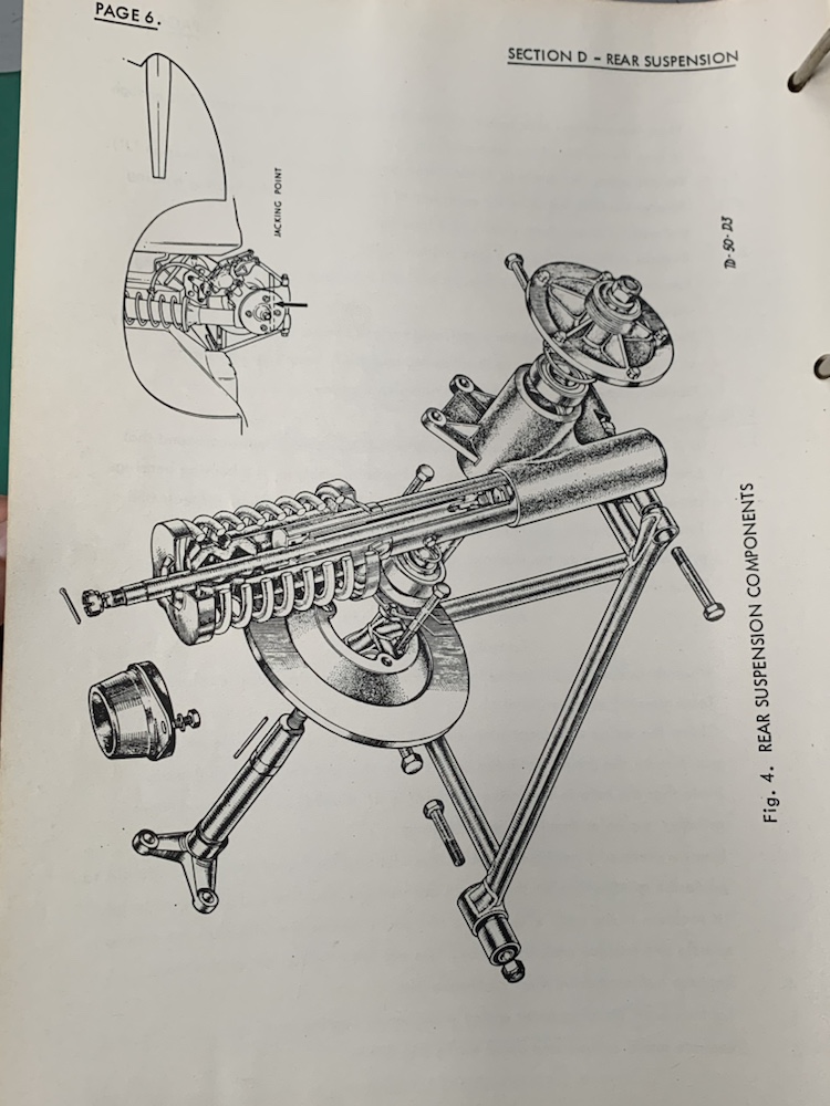
The exploded diagram from the workshop manual shows nicely how it all goes together.
The chassis tubes show some evidence of being modified. I don’t recall this area being a particularly tight fit with the gearbox but that’s the only reason I can see for doing this alteration.
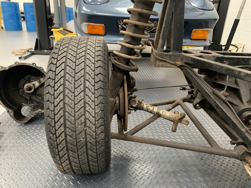
The rear wishbones feature zero adjustment for alignment, so a lot of faith/importance in the chassis mounting points. What I would call the hub is known as the bearing carrier in Lotus world. The lower damper tube is pressed in to the casting, the brakes mounted inboard. Up top there is a “Lotocone” top mount, essentially a rubber mount designed with a bit of give to allow the angle of the damper to change through the compression stroke.
Now came an interesting mission, removal of the knock off wheels.
There was of course the rubber mallet which lived in the car’s boot, not even close to budging them. Just knocked lumps off the mallet! Next up, bit of wood + 2kg club hammer. One smashed up piece of wood.
Gave up and ordered a tool off eBay, highly recommended by the Elan forum. Then I took the hump and really wanted them off, so one last try with a meter long section of 2×2 and an assistant to hold it so I could proper swing for it and not risk thumping the face of the wheel.
Success, just! Stopped at just getting them loosened off slightly, saved fully removing them for another day when it would be going on to axle stands for the suspension to be stripped.
Here’s an overview of the suspension I figured would be interesting with the Elan having such a reputation for handling
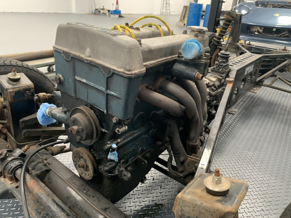
With the body and chassis apart, it was also time to pull the drive train.
On the face of it, you’d think it would be easy enough to haul the engine and box out with it this stripped down.
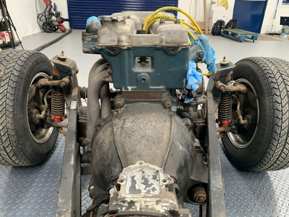
The headaches become a bit more apparent from this angle:
Vacuum tube crossmember to sump clearance
Exhaust manifold to chassis clearance
Transmission shift tower positioning between chassis rails
Decided this wasn’t going to work, so pulling the manifold off was more sensible. Interesting there is a redundant bracket and threaded fitting for a handbrake cable on the passenger side, presumably this is for LHD markets.
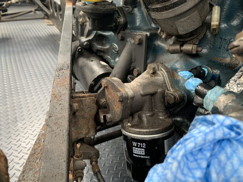
Not a lot of clearance around the oil filter and pump.
The starter motor and bell housing are actually in between the chassis tubes.
As well as the tight fit, there are some other foibles of note.
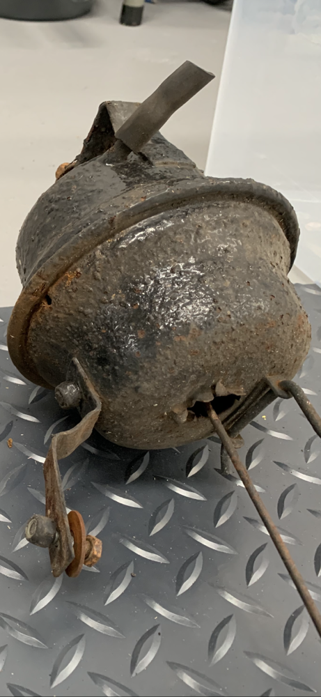
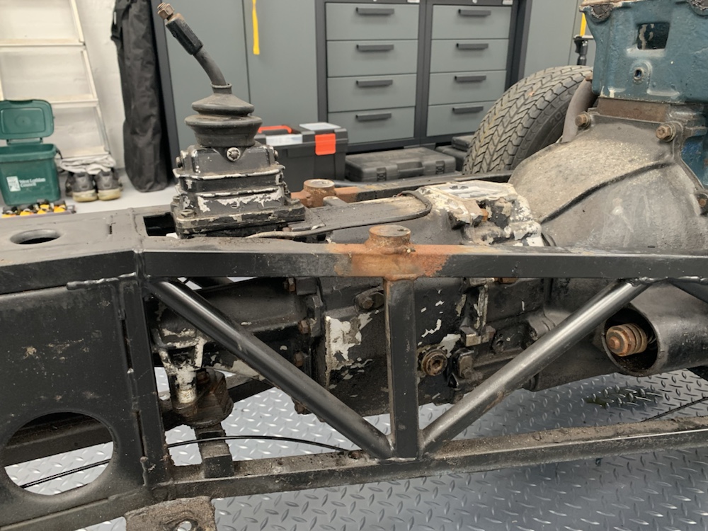
Don’t know why this section is so corroded compared to the rest of the chassis. These are the threaded bosses which the screws on the top of the transmission tunnel / bottom of the fascia panel thread in to.
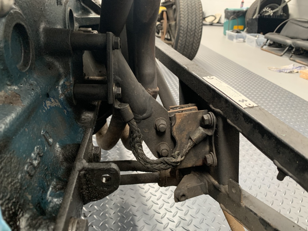
This is not a standard gearbox mount as far as I can tell. A section of solid bar has been welded on to the lower rails, slotted to allow the handbrake cable to pass through, and threaded to accept a rudimentary rubber mount.
All of this would be because our car isn’t running a normal Elan spec 2000e Ford derived gearbox. Our car has a 5sp ZF box more commonly found in droopsnoot Firenzas.
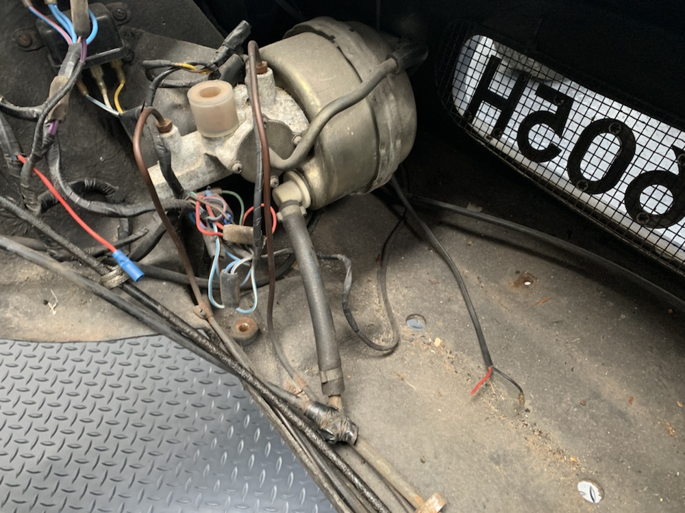
With the body shell off the chassis, it made some parts of the strip down process a lot easier. Everything in the nose area could now be accessed with the body raised to chest height and standing in the engine bay.
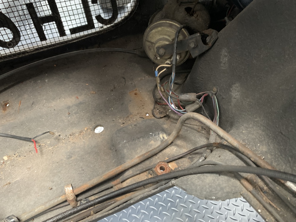
The brake servo is mounted front left, with the vacuum feed T’d off the line in to the vacuum tube on the chassis. On the other side, the little solitary horn, should probably have checked it worked before removing it actually!
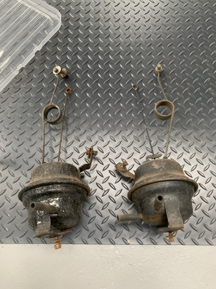
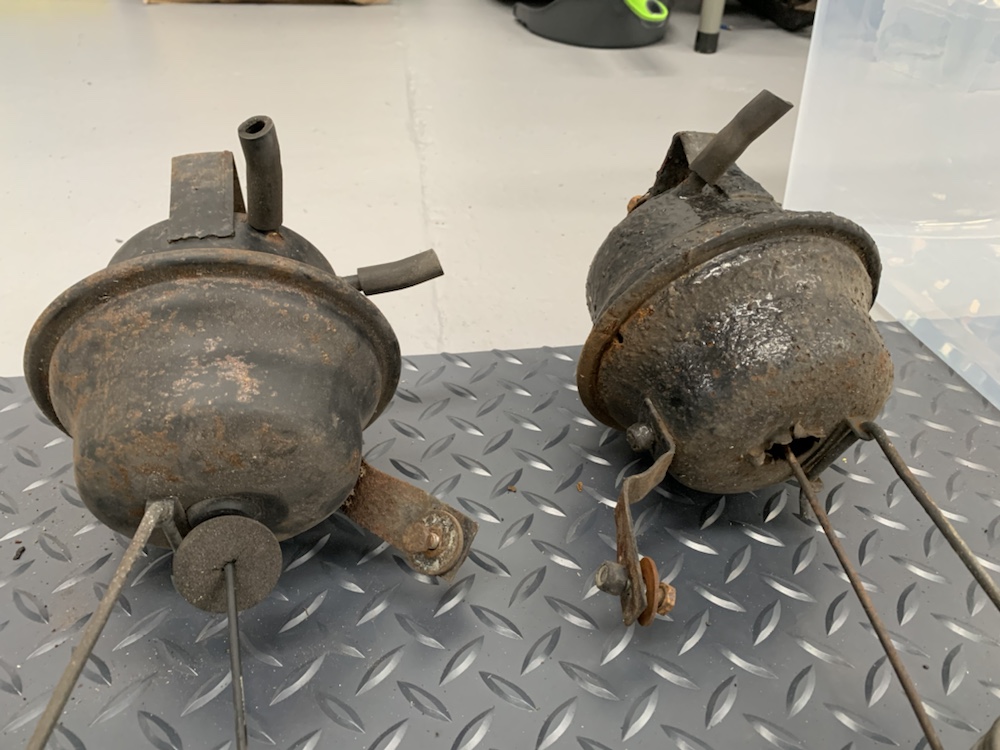
With those removed, next up was the headlight vacuum pods. The front left was evidently replaced when the car received the questionable quality accident repair on that corner.
As far as I remember, the headlights worked before parking up. That being said, a conversion to electric actuated units is quite common. Still a decision under debate.
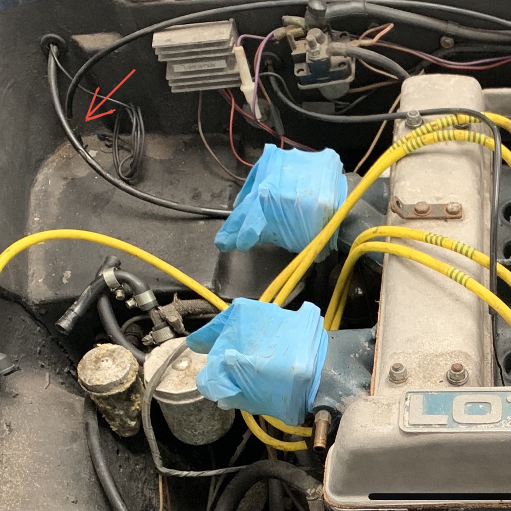
Grabbed some pics today to better answer a question raised on Pistonheads regarding the master cylinder orientation on the car.
On the face of it, they would look to be the wrong way round, with the brake and clutch cylinders positioned in the opposite order from the pedals.
This is due to the limited space available on the outside of the engine bay due to the inner wheel arch.
I’ve also highlighted the throttle cable with the red arrow in the picture, this enters the cabin vertically above the pedals.
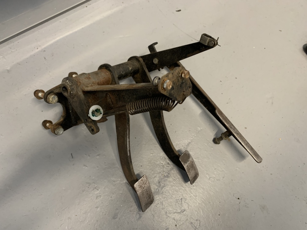
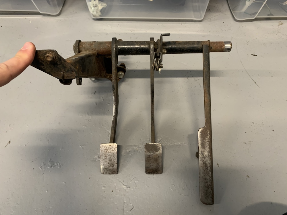
Here we have the pedals out of the car.
At the left hand side, the bracket with 4 bolts goes through the bulkhead and these bolts mount the master cylinders in the engine bay.
The clutch pedal attached directly to the piston rod from the clutch master cylinder. The clutch pedal rotates freely on its own.
The brake pedal is mounted on a rotating sleeve which actuates the brake master cylinder piston via the small lever at the far left, which also has the white plastic attachment for the brake switch on it and the return spring.
The accelerator pedal is also on a sleeve with the long lever connecting to the throttle cable underneath where it enters the cabin, so pressing the throttle pedal towards the bulkhead, move the lever down and pulls the throttle cable down vertically.
Clever way around the problem of mounting the master cylinders in the limited space available without ending up with massively offset pedals.


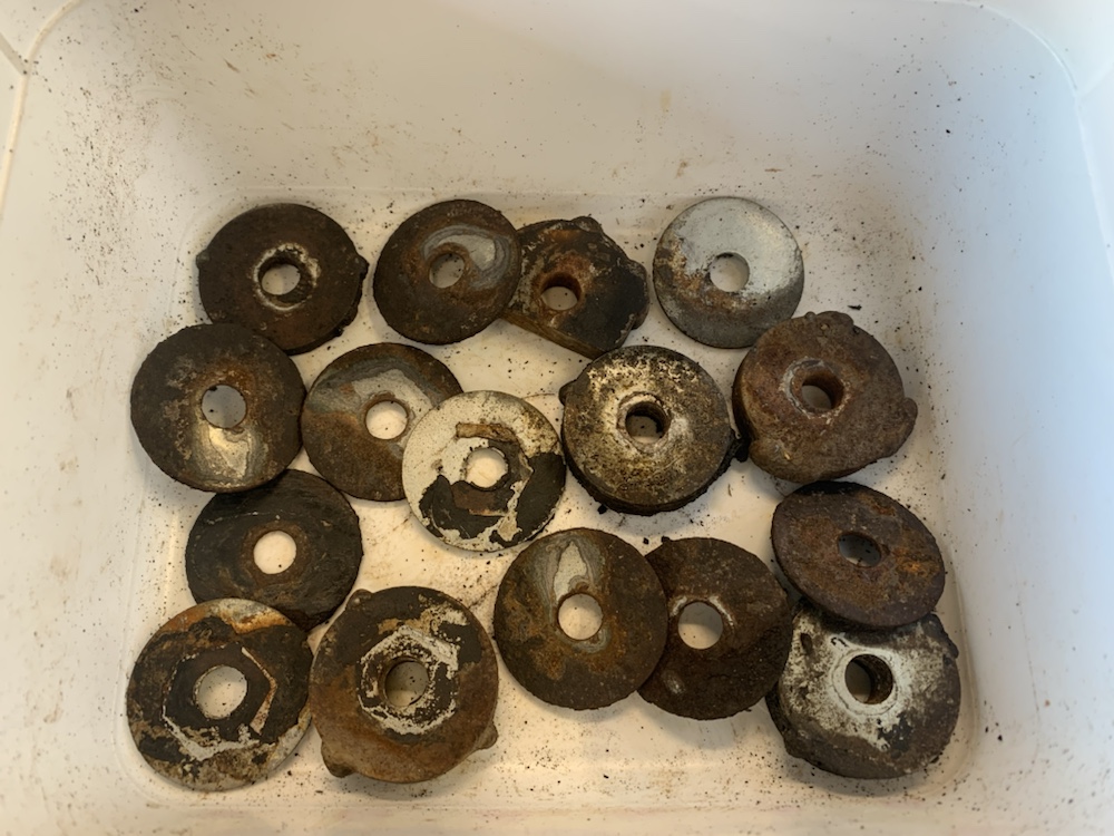
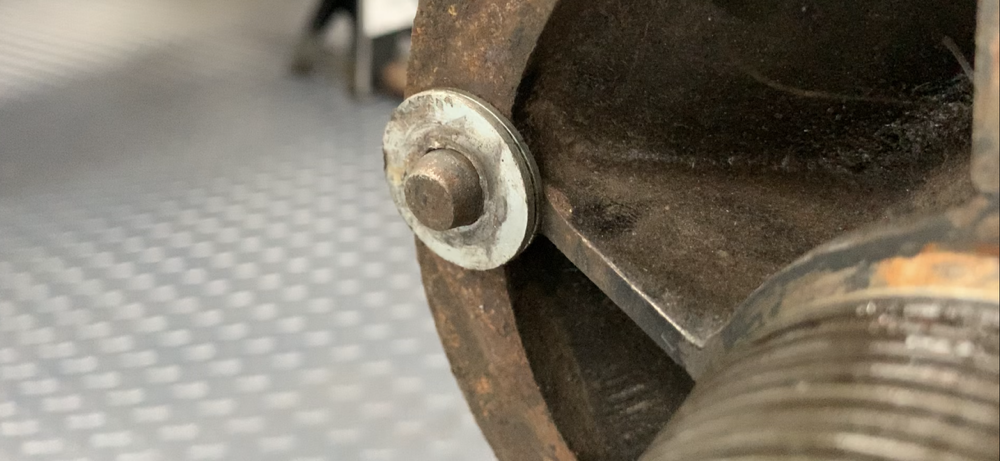 Yup, penny washers on the drive pegs!
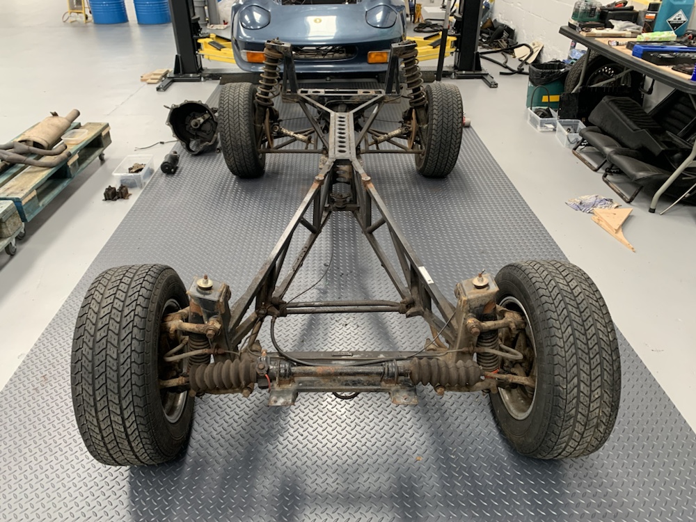 The steering rack on the Elan is mounted forward of the front axle line. The tie rods and rod ends will need replaced, rubbers weren’t perished but felt very old and will be replaced at the same time.
 The exploded diagram from the workshop manual shows nicely how it all goes together.
 Success, just! Stopped at just getting them loosened off slightly, saved fully removing them for another day when it would be going on to axle stands for the suspension to be stripped.
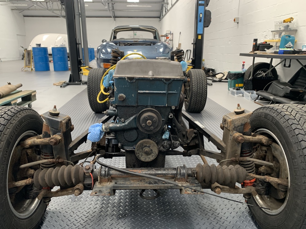
 Don’t know why this section is so corroded compared to the rest of the chassis. These are the threaded bosses which the screws on the top of the transmission tunnel / bottom of the fascia panel thread in to.
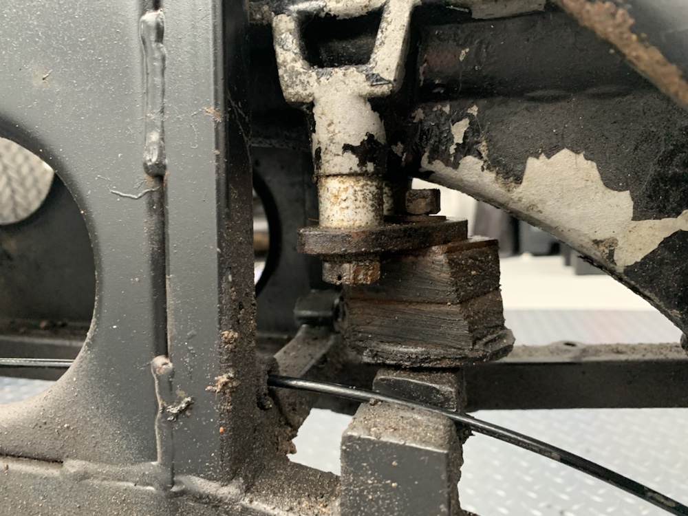 This is not a standard gearbox mount as far as I can tell. A section of solid bar has been welded on to the lower rails, slotted to allow the handbrake cable to pass through, and threaded to accept a rudimentary rubber mount.